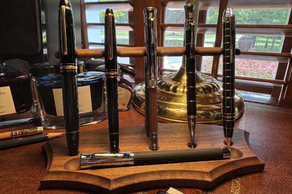
As a learning project for my new Shaper Origin, I am making a pen and pencil stand for my desk. The stand holds five writing instruments vertically, and a fountain pen horizontally.
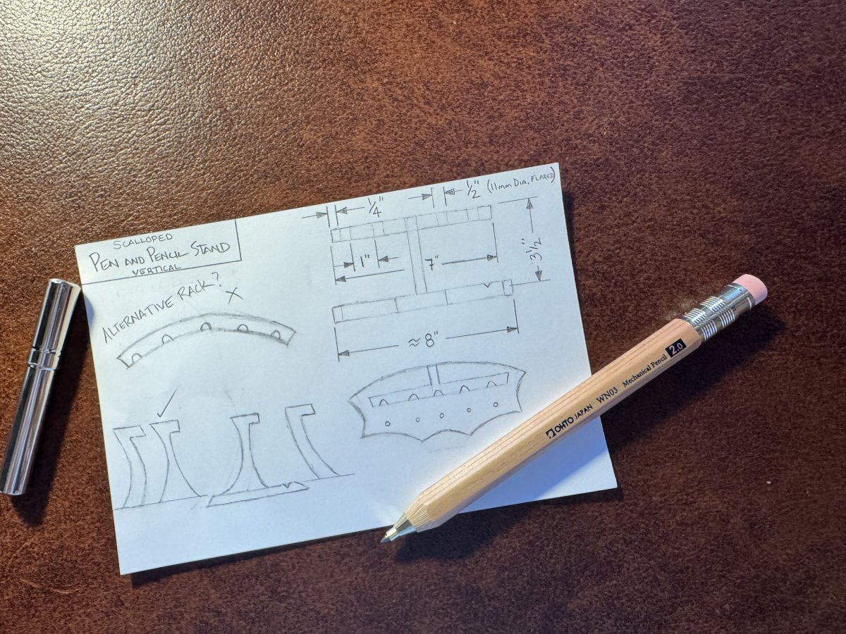
First, a sketch is made.
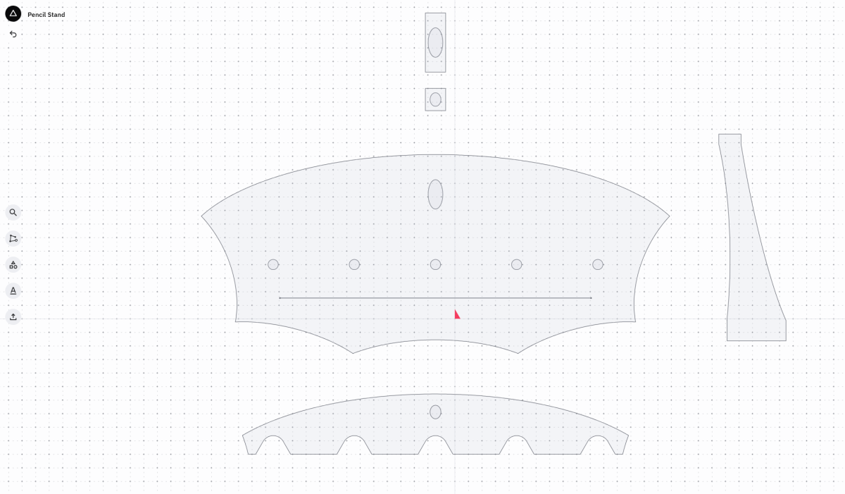
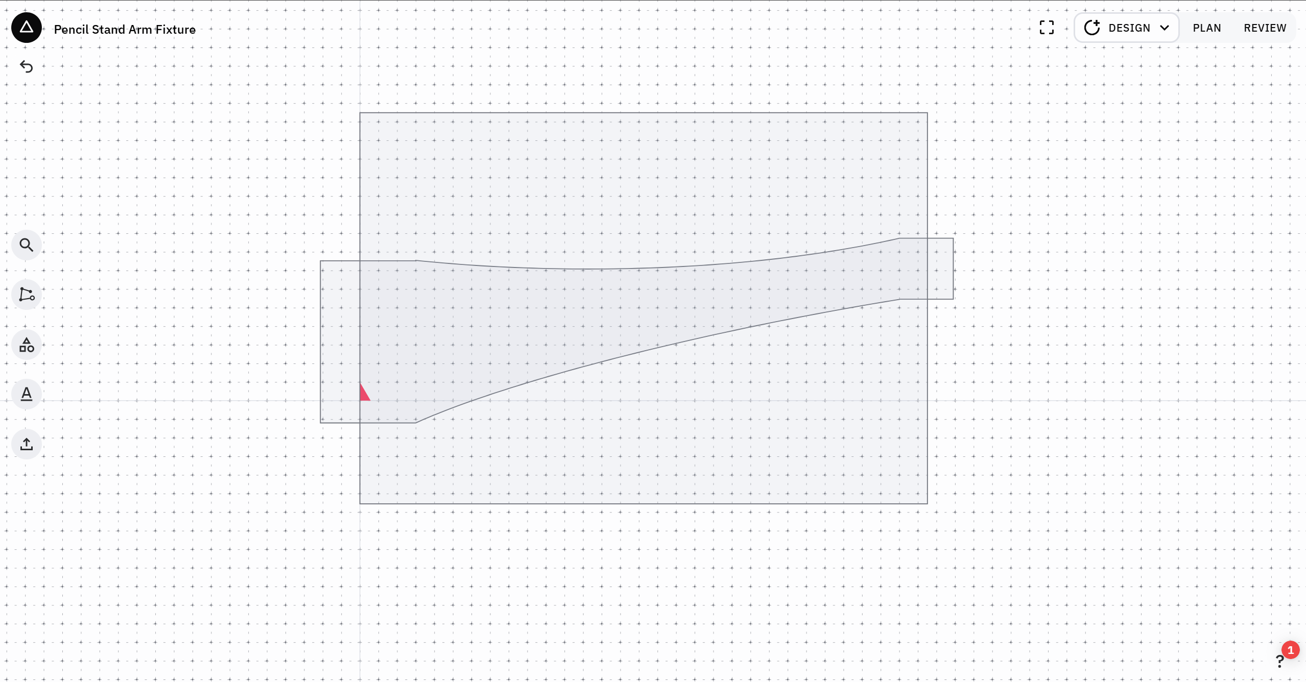
The design is refined in CAD using Shaper’s Studio tool.
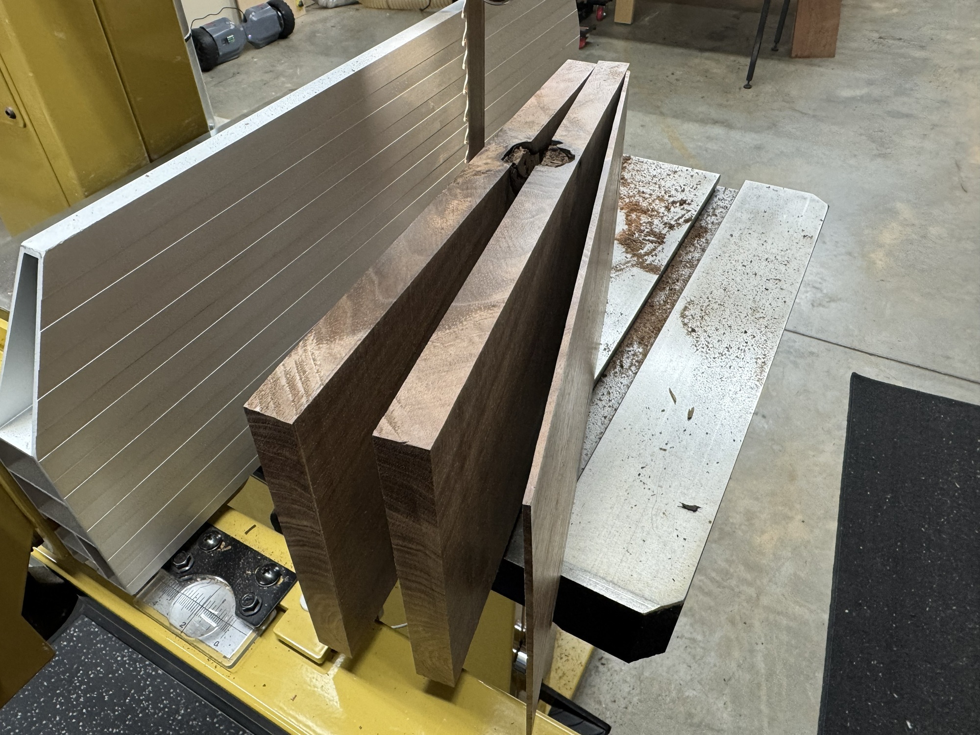
Some walnut scrap is resawn and milled for the parts. Extra material is milled for prototyping and refining parts.
Then some prototypes are made. After some experimenting with bits and cut depths, the CAD file is further refined and some notes are made.
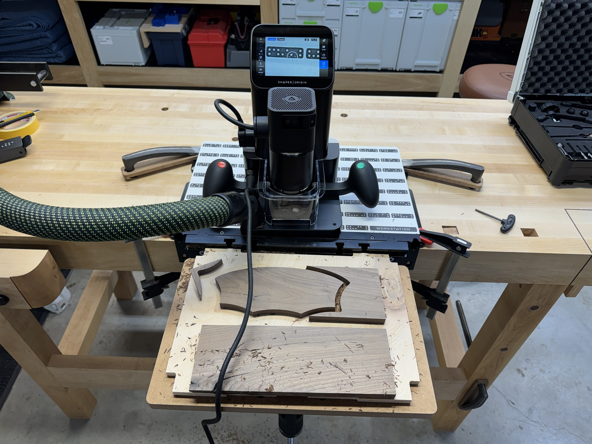
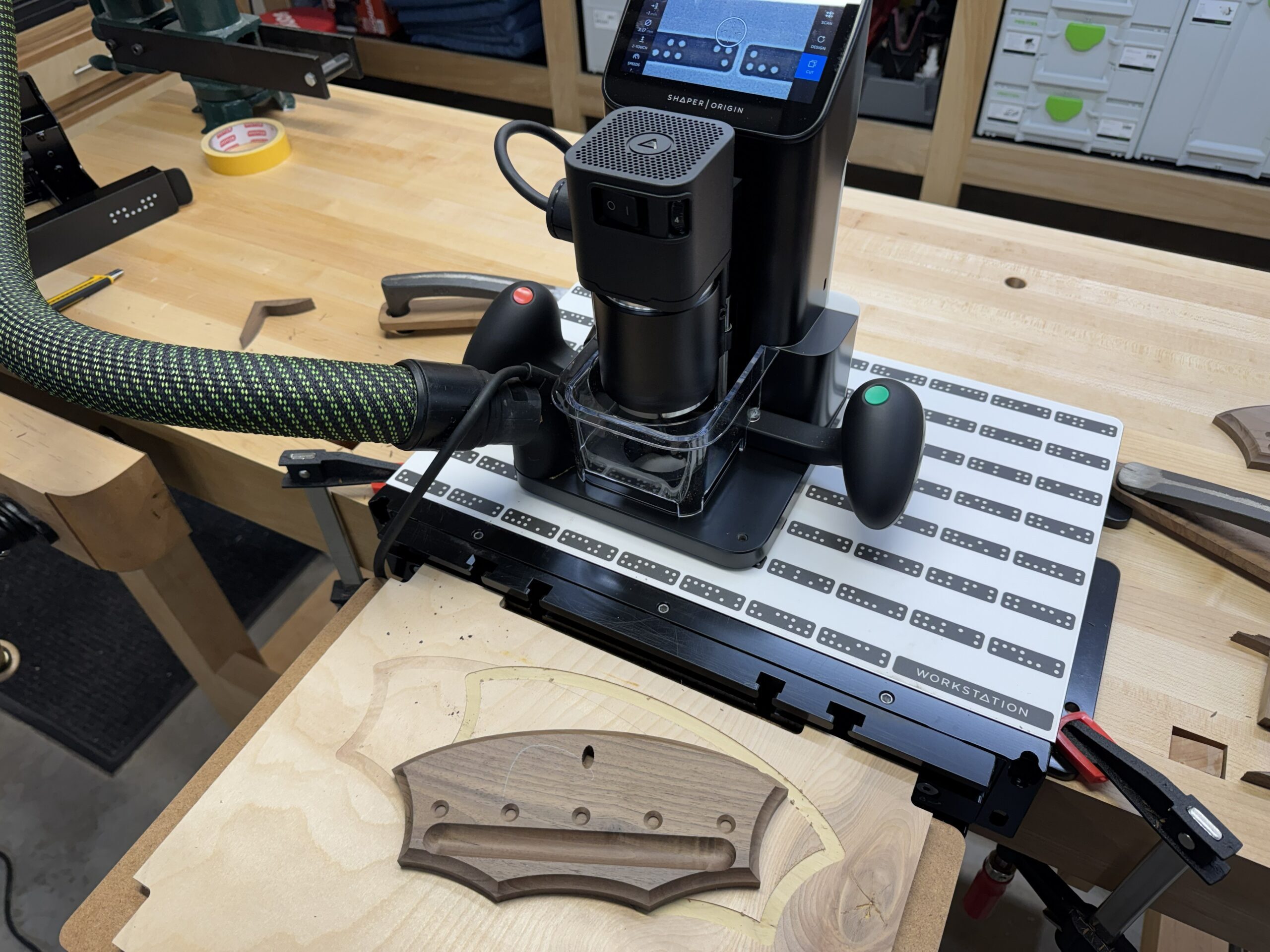
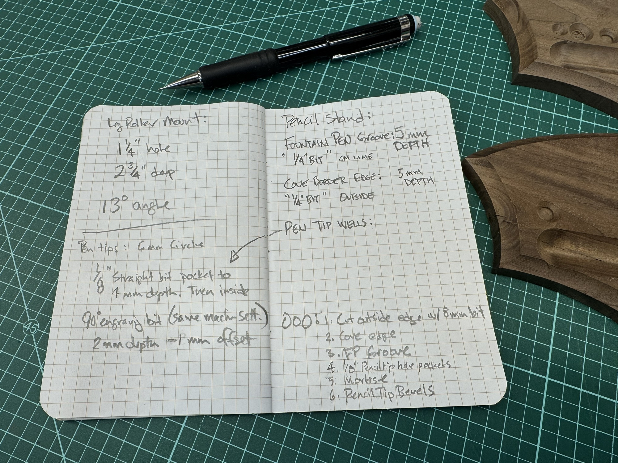
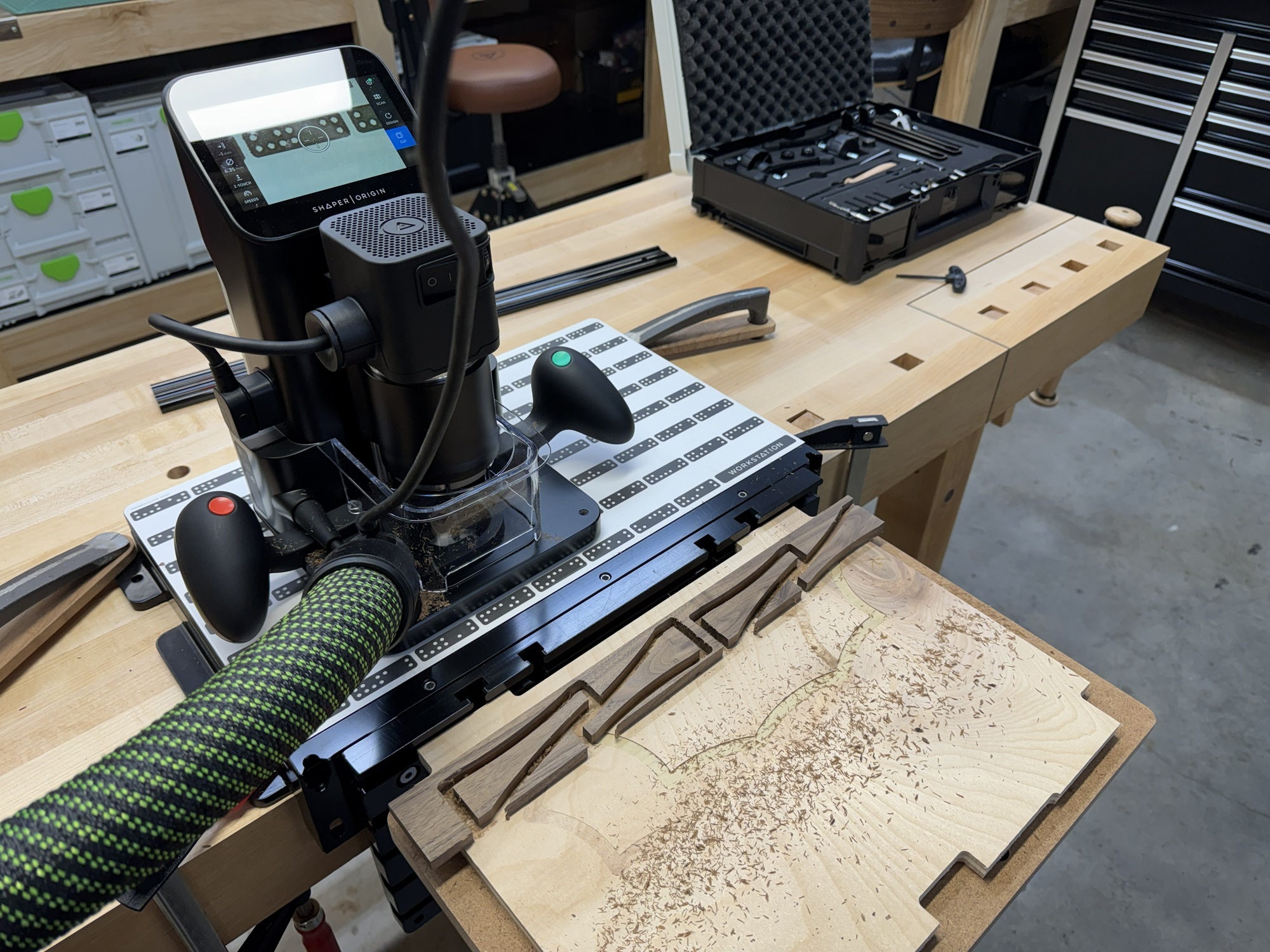
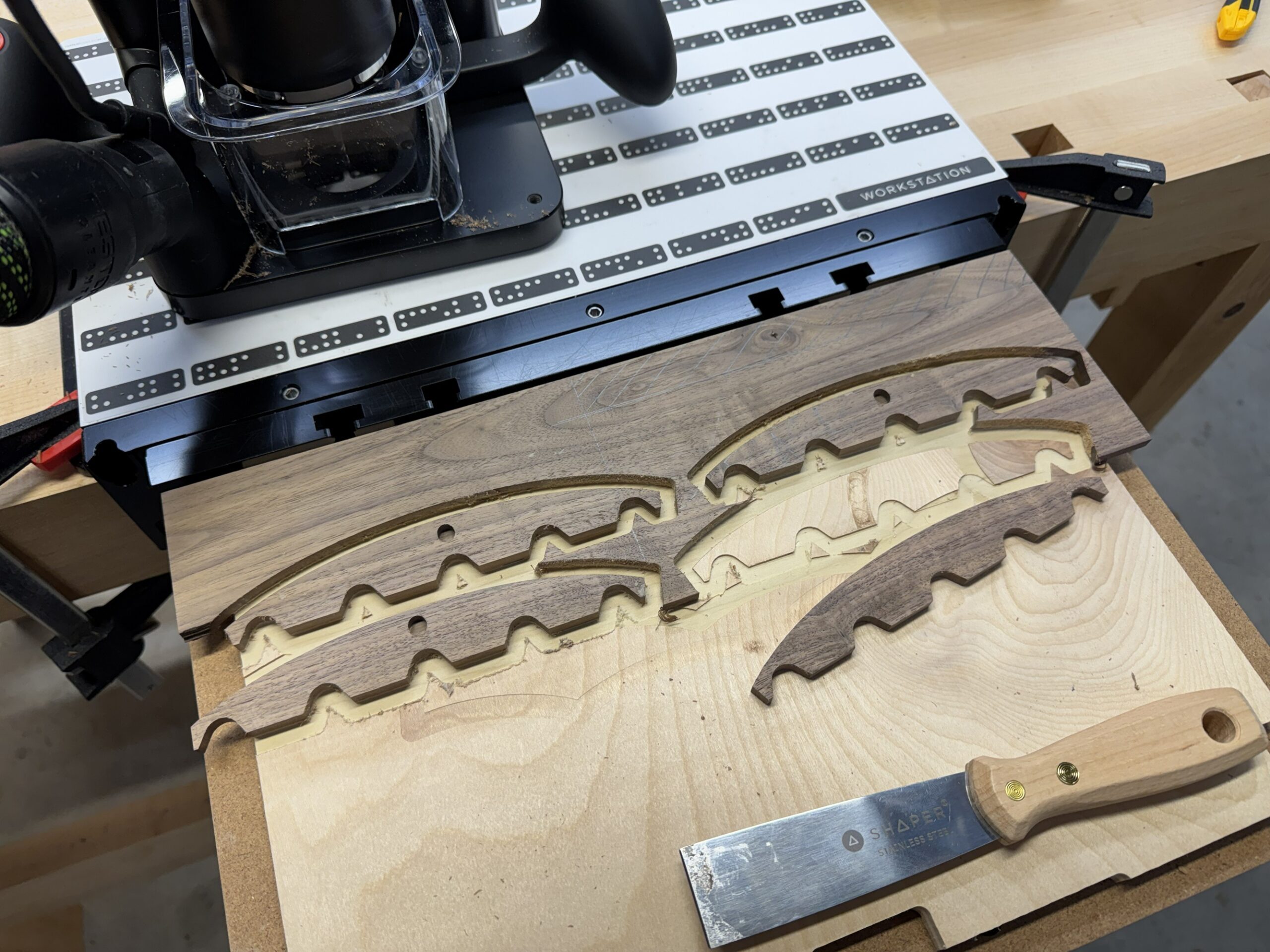
Iterating is so fast and easy on the Shaper. Making this project with pencil layouts, templates, and pattern routing would take so much longer, particularly when revising the design.
Since the Shaper is a CNC, making work fixtures for cutting joinery on these tiny parts is easy: you just cut the negative space into a block of wood.
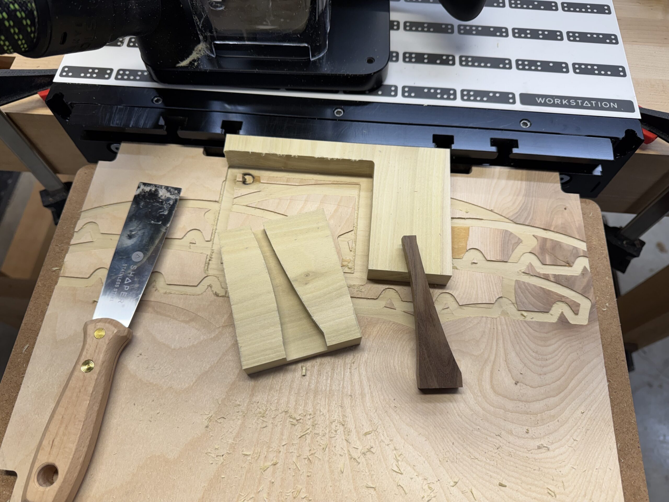
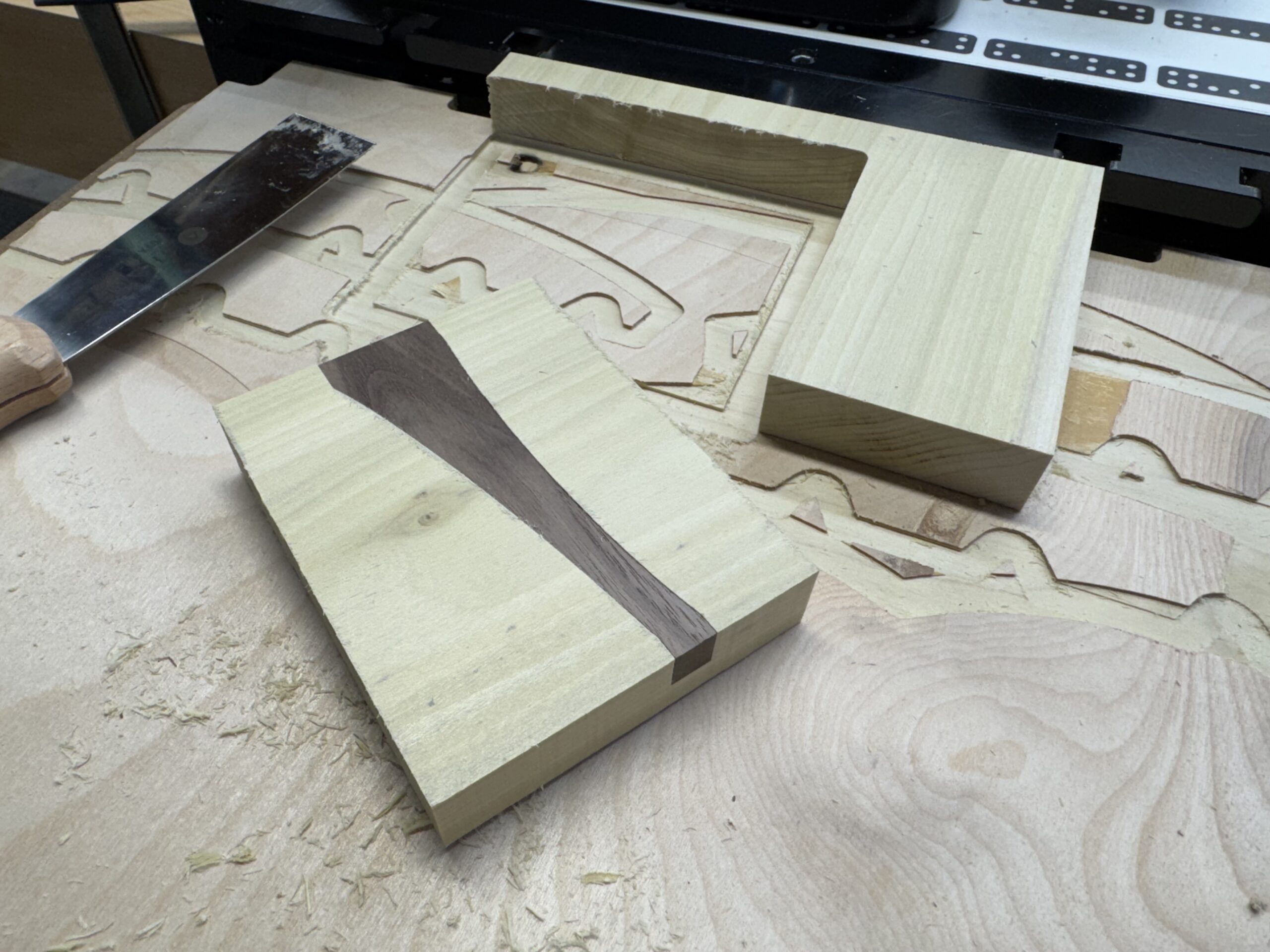
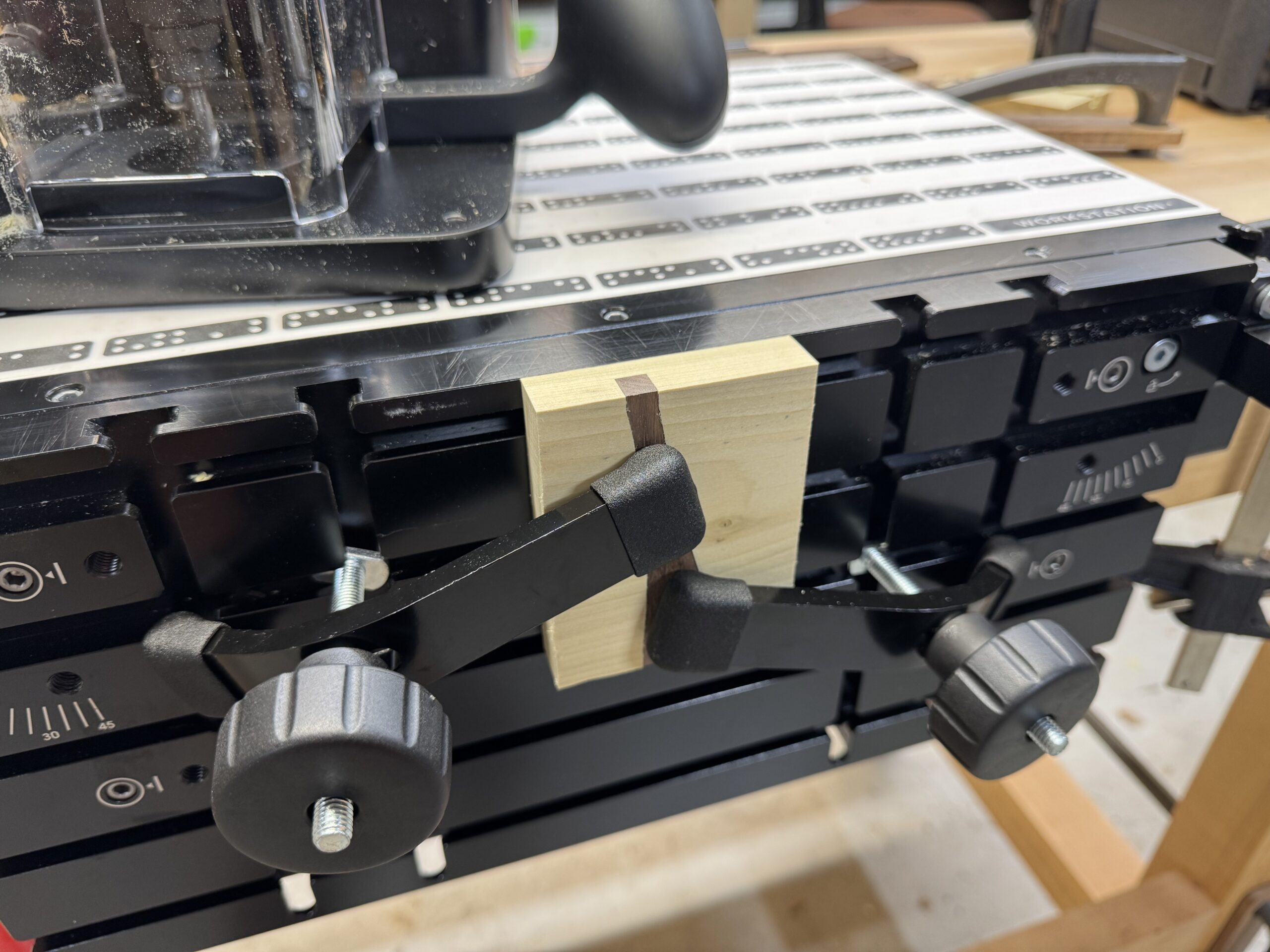
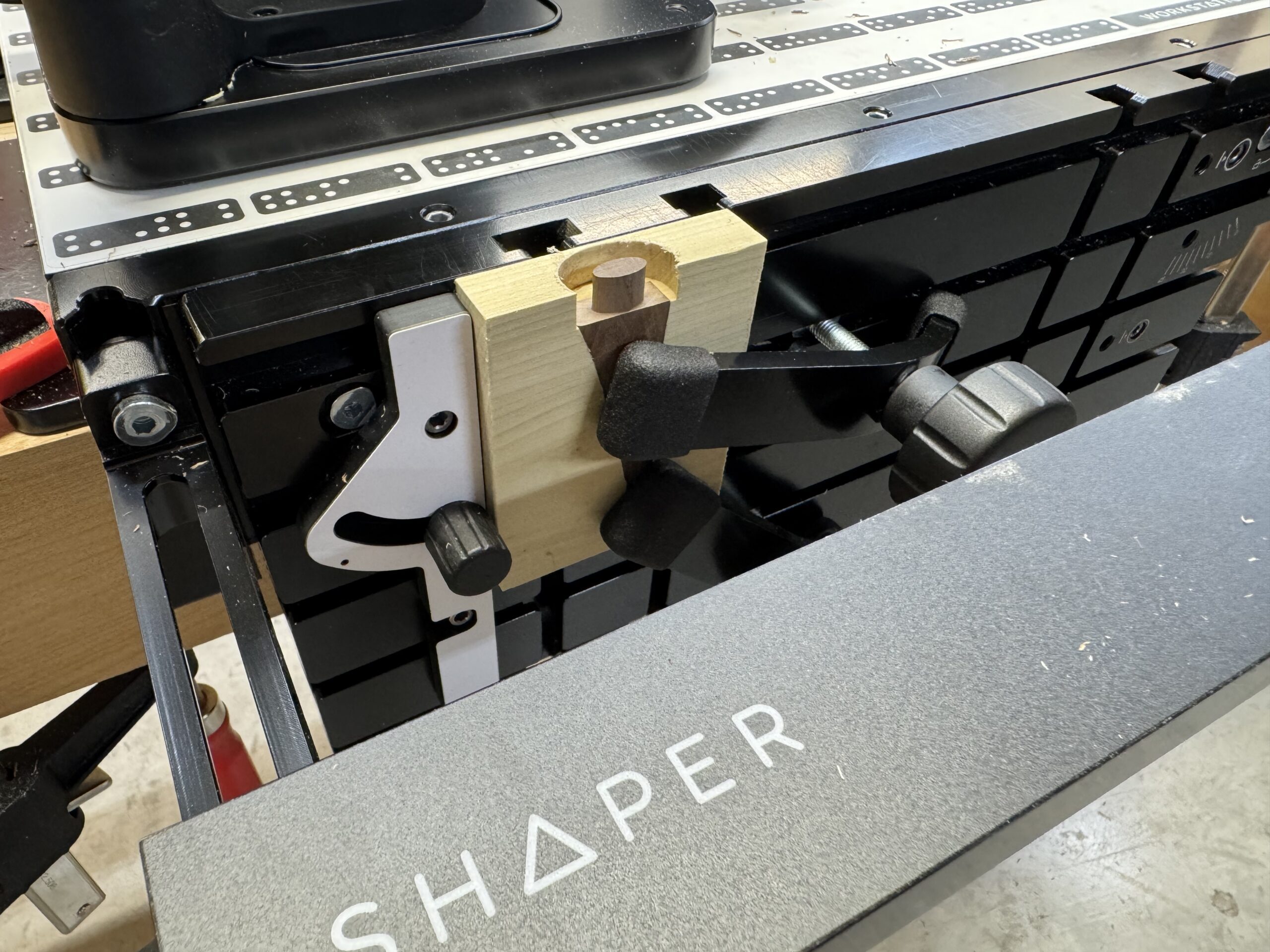
The prototype is completed. It almost works but the base will be scaled up a bit so the pen groove does not intersect the coving line, and the top of the leg will be made a bit wider.
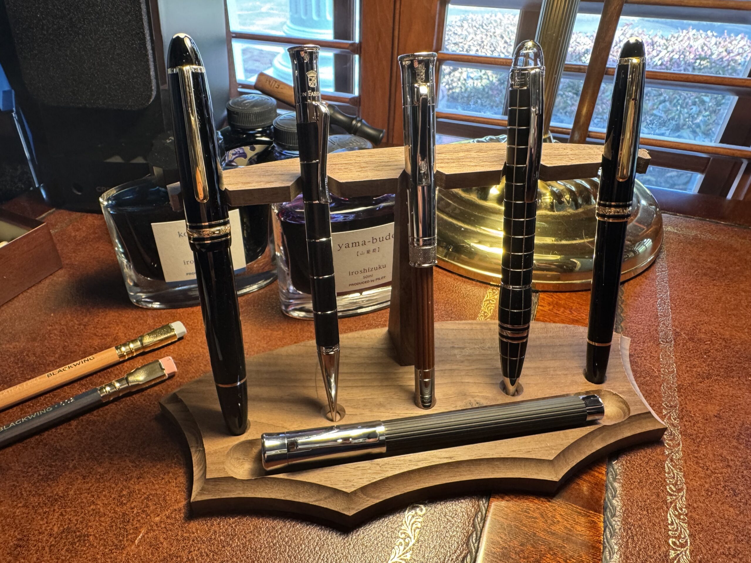
On to the real thing. The problems encountered in creating the prototype (all of which were ultimately figured out) were mainly caused by inattentiveness to the offset setting on the tool. It seems that if one relies exclusively on encoded offsets from the Shaper Studio CAD file, all is well. However, offset changes made on the tool itself to dial in a cut (e.g., when tuning up a tenon for the fit you want in the mortise) are “sticky” in the tool. Thus, when you move to the next cut, a prior offset setting made manually on the tool is not overridden by the encoded settings. This will scrap your part if you are not attentive to it.
Also, it makes things a lot easier if you plan your jig out with nice, even reference edge dimensions for repeatable fixturing.
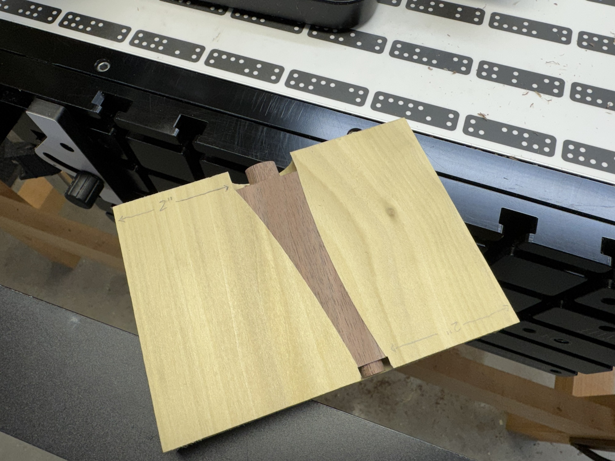
In any event, the final version of the stand went very well and the whole project was made in an afternoon, including milling the lumber. Additional units can be made quickly and easily with the final settings now saved in CAD. Here it is, right off the Shaper Origin:
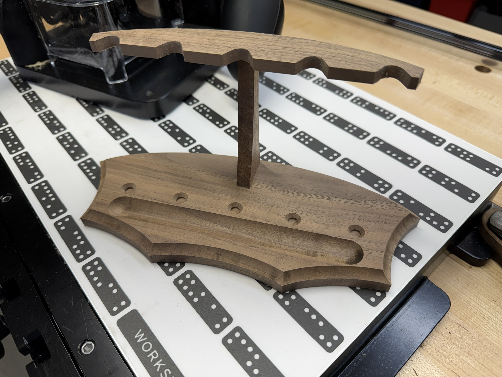
This was a really good project to learn the tool. It is small, so it can be made from scraps and mistakes don’t really matter. It is pretty complicated and requires use of every function/operation that can be done with the tool. It required three-dimensional modelling in the two-dimensional Shaper Studio CAD program. And it involved cutting joinery on very small parts with no square reference edges, which is one of the super-powers of this little tool.
Now to prepare the corners, sand, glue up, and prep for finishing. The corners on the leg and rack were rounded with a 1/8″ roundover bit on the router table, and the parts were sanded prior to glue up. Finishing before glue up was considered but rejected because the glue area on these tiny joints is minimal. They will not experience much load, but the priority was placed on maximizing the effective glue area (including the shoulders) rather than finishing convenience. A wipe on finish will be used, so finishing the stand assembled will not be much of a challenge.
Here it is glued up and drying.
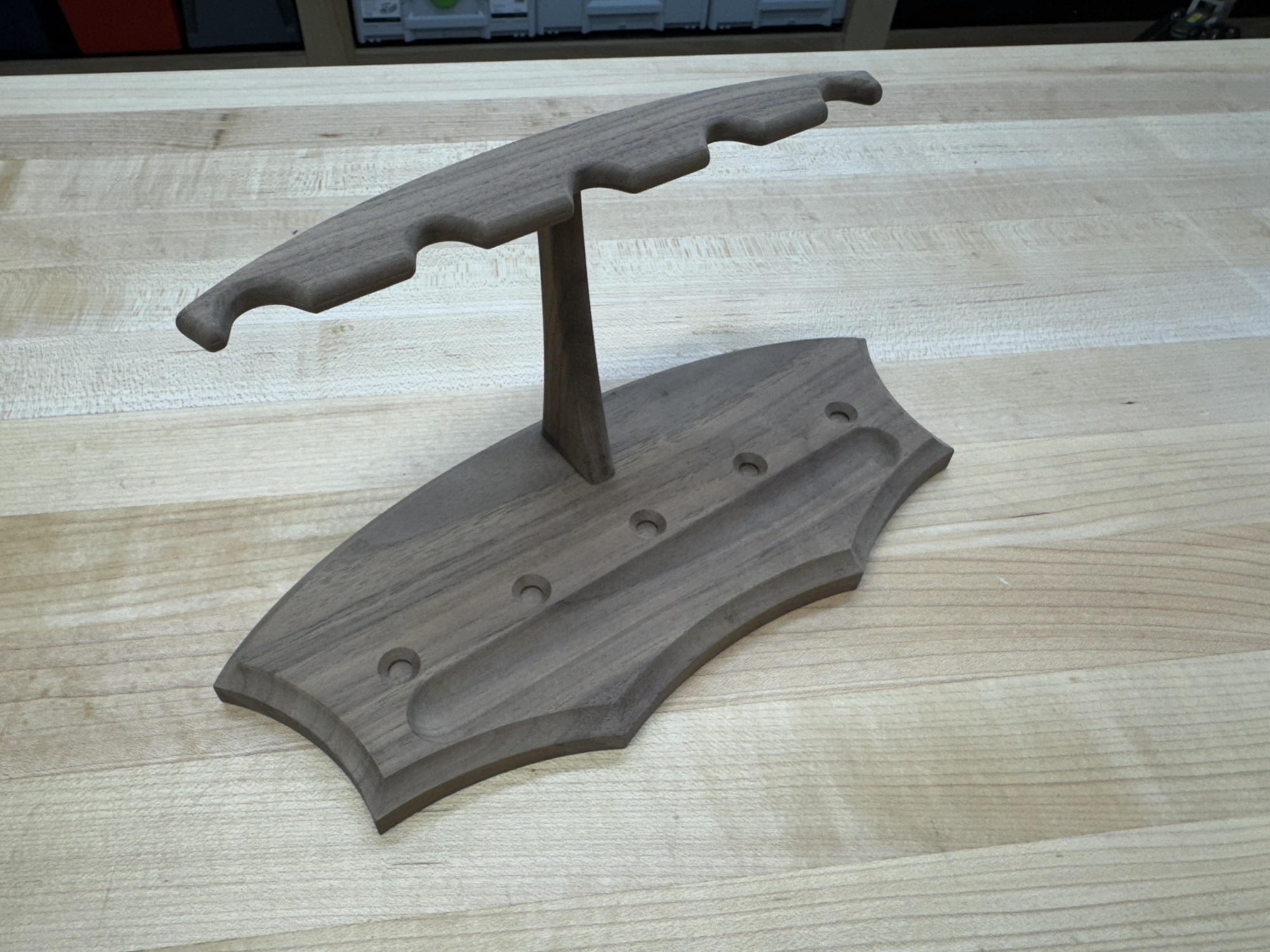
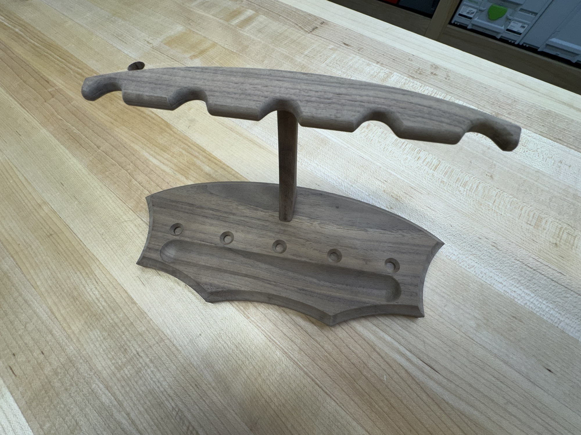
The stand is finished with Rubio Monocoat hard wax oil.
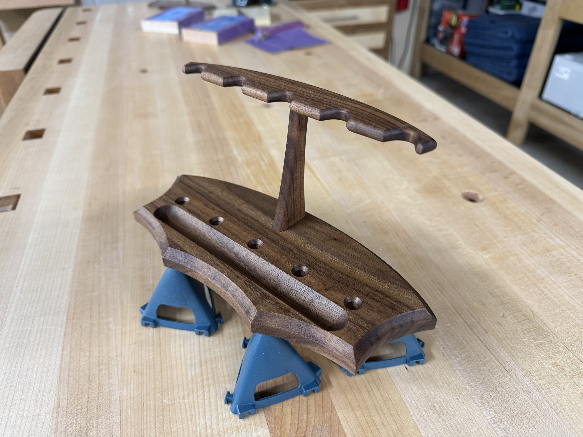
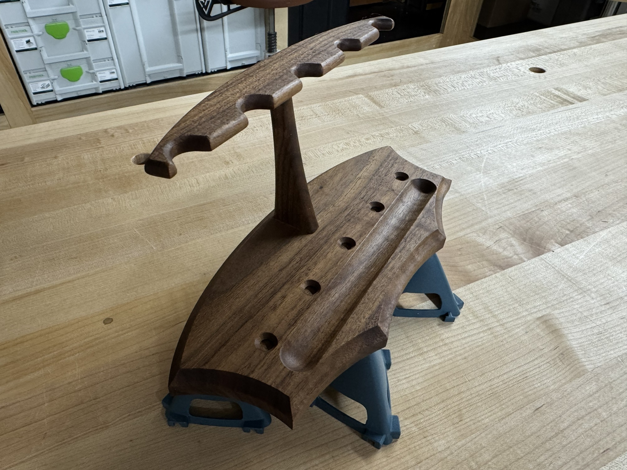
Done!
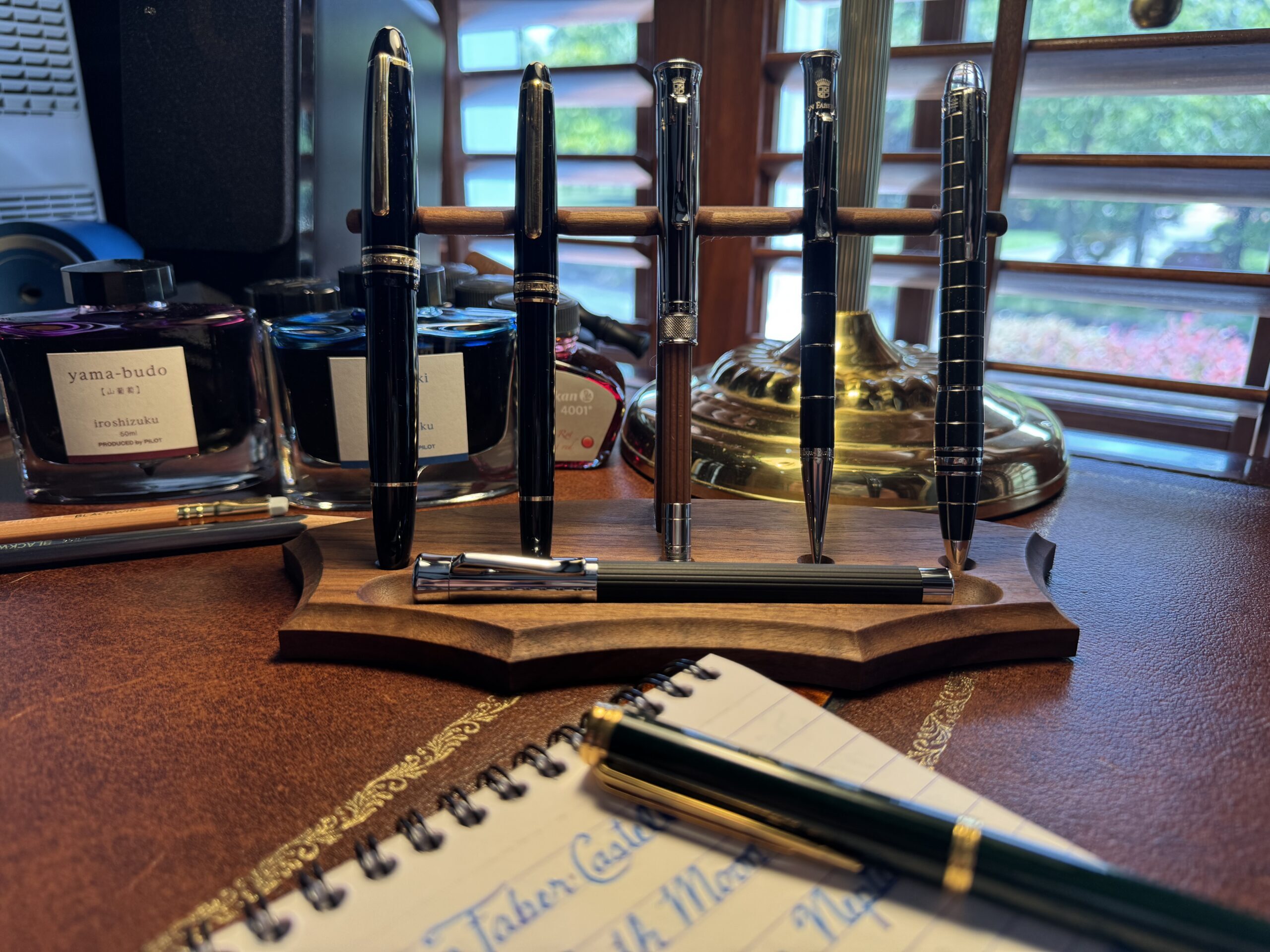
Thanks for your interest.